Last week, I received a phone call from a good friend of mine. He had been installing a sprinkler system in his backyard. He had recently purchased a new construction home with nothing in the backyard. He didn’t have any experience installing these systems, and electrical setup is never fun unless you know exactly what you’re doing. So obviously, I agreed to help in exchange for a case of beer and pics for this post!
Let’s start with the layout and ground conditions. In Nevada, desert conditions usually lead to a dry environment, so he must be picky with the type of plants and grass he wants to have. The biggest issue with a new construction home like this, is that the backyards are not finished with anything except maybe a concrete pad for a small patio. Further research into the area will show a small layer of sand and topsoil, followed by caliche which is a type of clay. This clay is tough to dig by hand, so power equipment will be required to save your back and time.
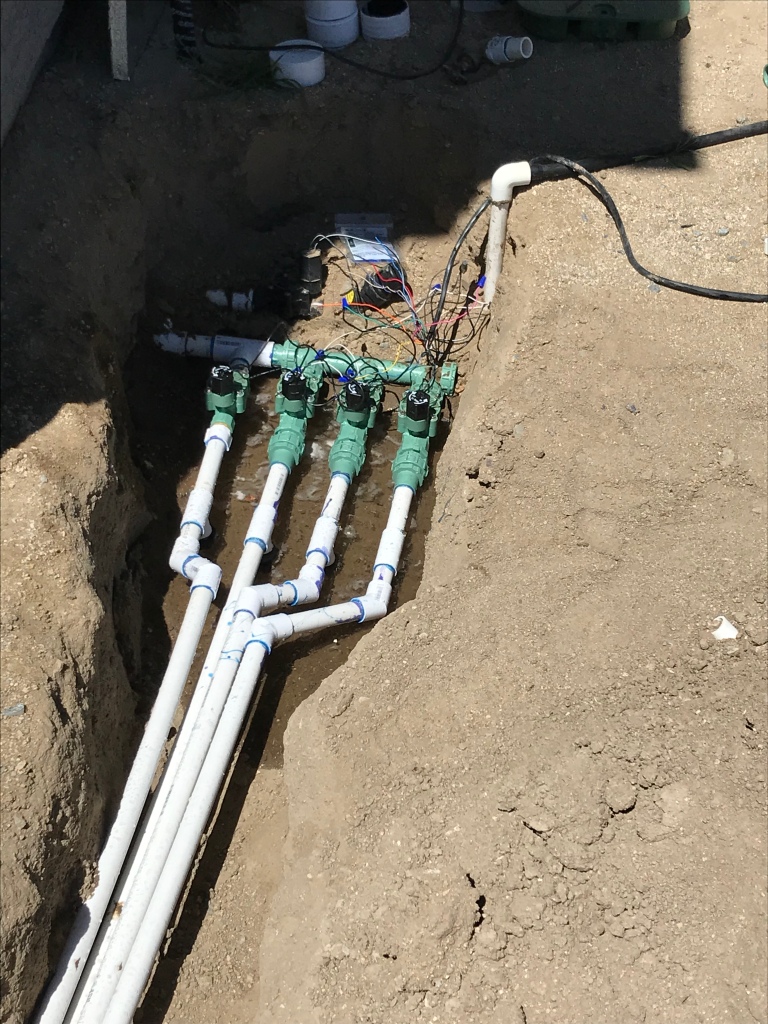
This clay will come into play with a later blog, but for now, he had already dug up trenches for his sprinkler system and mapped out zones. 4 zones were to be used to supply a grass area and two garden drip systems. Everything looked great based on my first walk-through with him. With this looking good, I moved on to inspect the manifold and controller.
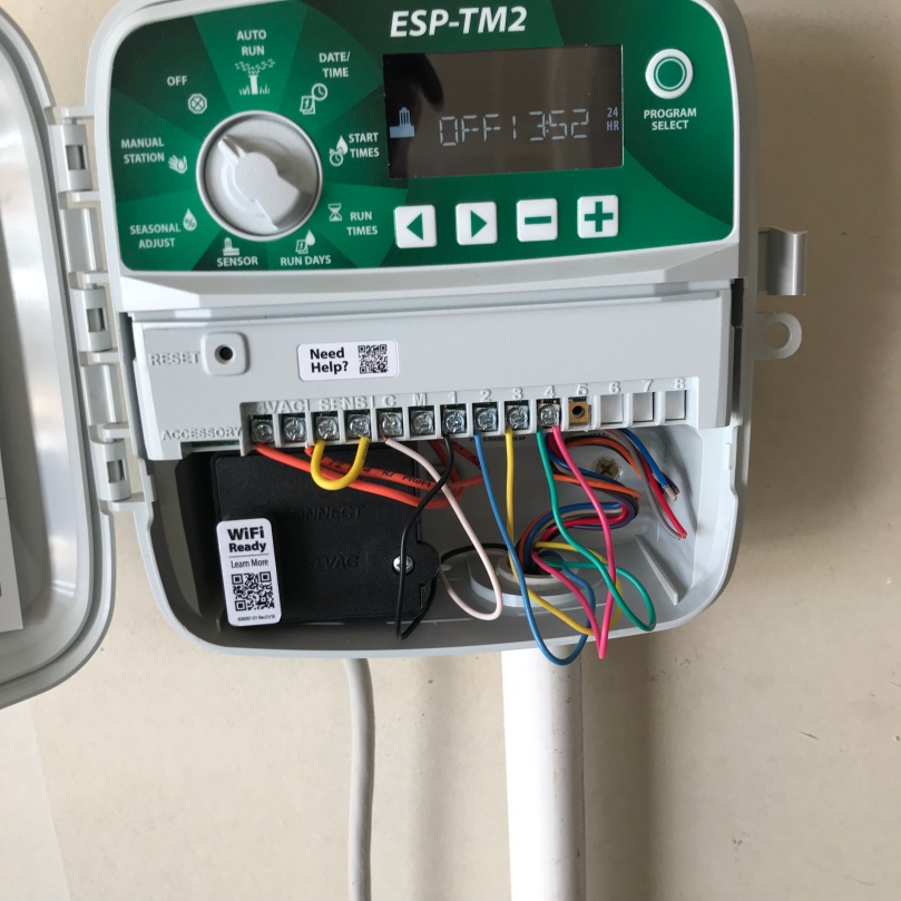
The manifold looked nice and clean, and I was happy about that because it will let us know if anything is wrong during testing. The controller was a different story since he had a manual with instructions for wiring up to 12 stations, but only had 4 stations available. Turns out that the original contractor gave them the wrong manual, this comes in to play later.
Science note: Let’s talk about electrical fundamentals for a minute. Sprinkler valves are controlled by an electrical signal, Direct Current specifically, that cycles a solenoid valve that opens when energized. The valve opens, allowing water to flow at around 70-150psi depending on supply pressure and any reducers in the system. As the signal stops, the valve is spring closed shut. This is an important concept since you need to have the wiring exactly as shown in the diagrams to operate correctly.
Since the controller was only programmed and built for four zones, my buddy will have to make some decisions about his setup and materials. The controller was originally installed with one zone in the front yard, so that means he would have five zones. He could spend over $100 on a new controller, and then wire it and test it, or he can change his zoning. He decided to place the grass areas on two separate zones, then have both drip systems controlled in one zone. This is the cheapest solution to his controller and zone problem.
Wiring this controller to the valves is easy and takes 2-caps per zone and some 18-gauge wire, pictures are below. He already had a 12-zone wire routed to the manifold, so picking the colors to the zone is the hardest part. Walking the system to make sure my zones were correct, then wiring the positive and ground took about 5 minutes each. Labeling the wires to the zone is a good practice to start, sometimes you can remember the colors to the zones, but to be safe and consistent I label them.
Electrical Note: The more current and voltage that goes through a system, the larger diameter wire you want. Remember in my previous blog I talked about the bigger diameter, the smaller the gauge of the wire. In this case, the current and voltage are relatively small. Since the valves are commonly used, it’s a 24-volt, Direct Current (DC) system. The controller itself is powered by a typical 120-volt Alternating Current (AC), which is why you plug it into the closest outlet.
Once wired, we get to test everything. Start with the header supply to the manifold, which is the water main to the system. I wrote a blog a couple weeks ago about this process, check it out here. Check for the connections and for any leaks.
Since the manifold was good, we started checking individual zones. You want to turn it on manually and walk the system before back-filling the lines. Check sprinkler heads too, it’s much easier to fix without tools before they get buried. We ended up having to tighten a couple joints at the manifold, but nothing major.
Lesson Learned #1: Before testing the sprinkler system, adjust the sprayer to the direction of the lawn. You will be one wet pup when you jump and dodge water streams as you adjust the spray patterns.
Once each system is verified and tested, back-fill the trenches. Make sure to fill any voids under the pvc before filling the top. Add about 1-2” of extra soil on top of the trench since it will settle. As for compacting the soil, you can use a jumping jack which is super-efficient, or you can walk the trench since you exert a decent pressure on the trench to compact. You might want to compact the trench in multiple lifts, depending on the depth, this will help with long term settling of the soil.
That’s it, some easy wiring and his sprinkler system is running great. When it comes to materials, the most expensive part of the control system is the controller and wiring, which he already had. Connectors are relatively cheap at about $5. Labor for wiring took about 30 mins, which at an electrician rate would be about $50, using around $100 an hour. Lawn companies will give cheaper rates but they also might chart an initial show-up fee. Total cost for him was a case of beer and some wire and connectors, $30. Total savings for him was $20, plus he got a ton of manual labor in the form of shoveling and my back still hurts!
If you have questions or comments, leave them below! Subscribe to see more cool DIY projects coming up!


I’m glad that you mentioned that power tools will be needed for harder soil. I would think at that point that it might be worth it to step a bit extra to have someone come to dig the trenches for you. Hopefully, that would let you work on other parts of the system as well and get done faster.
LikeLike